CNC Fiber Laser Maintenance is the primary factor determining the operational lifespan and cutting precision of high-power industrial laser systems. As output capacities scale to 12kW and above, micro-level deviations in optical purity or mechanical alignment rapidly escalate into catastrophic component failures. At Jinan Allwin CNC Machinery Co., Ltd. (Fwincnc), maintaining stable cutting metrics across Desktop, Ground Rail, and Gantry laser configurations requires strict preventative protocols that isolate optical, thermal, and kinematic variables.
1. Protocols for Optical Protection in CNC Fiber Laser Maintenance
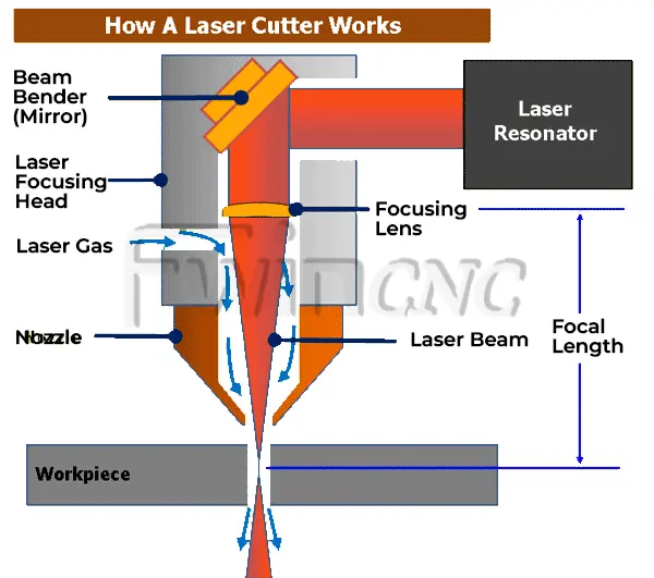
The internal optics of a laser cutting head—specifically the collimating lenses, focusing lenses, and transmissive protective windows—operate under intense energy densities. Contamination within this optical path is the root cause of thermal lensing, wavefront distortion, and premature lens destruction.
To execute effective CNC Fiber Laser Maintenance on the optical assembly, operators must manage the ambient environment during consumable swaps. Particulate contamination as small as 5 microns can absorb sufficient laser energy to crack a protective window under high wattage.
All optical servicing must occur inside an enclosed, static-free clean box rather than on the open fabrication floor. Cleaning procedures require 99.9% high-purity isopropyl alcohol and laboratory-grade, lint-free optical wipes. Operators must wipe in a single, unidirectional motion from the center of the lens outward. Circular wiping patterns drag abrasive airborne particulates across the surface, permanently scratching the anti-reflective coatings.
2. Chiller Fluid Dynamics and Thermal Calibration
High-power fiber laser sources and cutting heads rely on dual-stage refrigeration chillers to dissipate structural heat. Inconsistent thermal management directly compromises the laser beam quality and wavelength stability.
A core component of CNC Fiber Laser Maintenance is monitoring the electrical conductivity and temperature parameters of the cooling water loop. The chiller uses deionized water to prevent electrical arcing within the laser architecture. The conductivity of this fluid must remain below 10 micro-siemens per centimeter. If conductivity rises, the fluid must be flushed and replaced to prevent mineral scaling inside the narrow cooling channels of the cutting head.
Furthermore, temperature settings must be strictly calibrated. The optical cooling loop must be maintained at a steady 22 degrees Celsius to 25 degrees Celsius, matching the ambient dew point of the manufacturing facility. If the water temperature falls too far below the ambient room temperature, condensation forms instantly on the exterior surfaces of the laser cutting head when the machine is paused. This condensation migrates into the sealed optical chambers, causing immediate beam scattering and structural damage upon subsequent laser firing.
3. Mechanical Kinematics and Guide Rail Synchronization
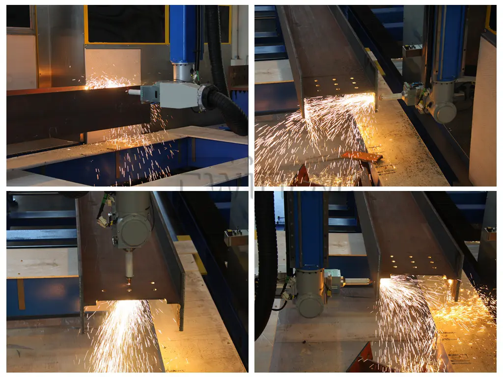
Maintaining mechanical tolerances across heavy-duty systems, such as Fwincnc Ground Rail Fiber Laser Cutting Machines or Plate and Tube Integrated configurations, requires rigid structural calibration.
Over extended operational cycles, the high accelerations of linear motors or AC servo drives introduce structural vibration that can loosen mechanical fasteners along the X and Y axes. Operators must execute scheduled checks on the helical rack-and-pinion systems. Backlash tolerances must be verified using a dial indicator; any clearance greater than 0.03 mm requires real-time adjustment of the gearbox tensioning mechanism to prevent geometric distortion during high-speed cornering interpolations.
4. Standardized Protective Window Replacement Protocol
To preserve the internal optics during standard field adjustments, maintenance staff must enforce a contamination-free replacement sequence.
Diagnostic Matrix for Laser Maintenance and Failure Analysis
| Failure Phenomenon | Underlying Root Cause | Corrective Maintenance Action |
| Incomplete cuts at outer sheet boundaries | Alignment drift between the laser beam axis and the nozzle center | Execute a tape-shot alignment check; adjust manual centering screws on the nozzle tip. |
| Striations on stainless steel cut edges | Turbulent assist gas flow caused by nozzle orifice deformation | Replace the copper nozzle; check dynamic nitrogen pressure stability at the regulator interface. |
| Fluctuating cutting depth during long runs | Thermal focus shift resulting from a contaminated protective window | Replace the protective window following clean-room protocols; inspect the upper focusing lens for burn spots. |
| Asymmetrical cutting quality (Left vs. Right) | Divergence of the fiber optic cable delivery angle | Inspect the QBH connector interface; verify that the fiber delivery cable is free of tight bends. |
By treating CNC Fiber Laser Maintenance as a rigorous calibration process—enforcing pure fluid metrics, maintaining Class 100 optical cleanliness standards, and neutralizing kinematic backlash—operators using Fwincnc Heavy-Duty Industrial Systems can ensure consistent kerf dimensions, low gas consumption rates, and extended lifetimes for expensive optical components.