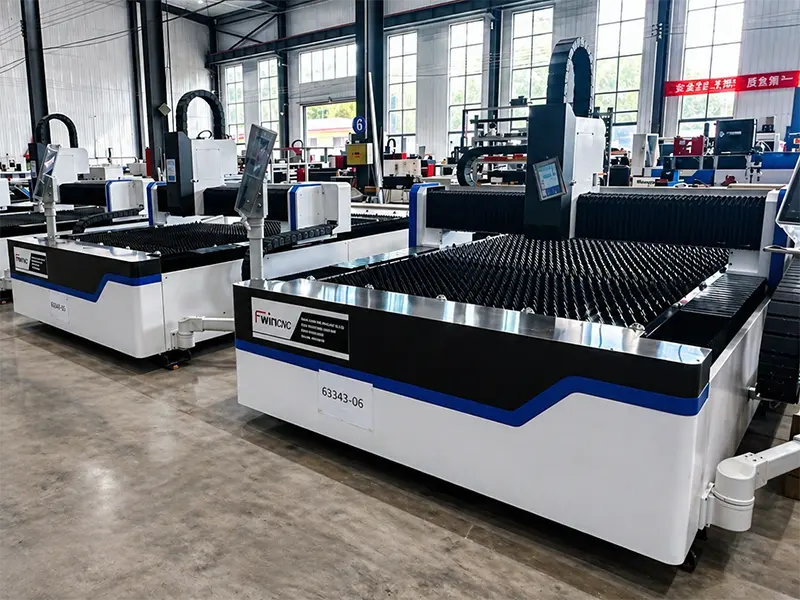
1. Physical Mechanics: How Pulsed Laser Spot Welding Operates
The operational core of a Pulsed Laser Spot Welding Machine relies on delivering high-intensity light pulses over milliseconds (ms). The process converts electrical energy into concentrated optical energy, focusing the beam down to spot diameters as small as 0.1 mm to 2.0 mm.
When a single pulse hits the target substrate, the localized surface metal melts instantly, forming a precise molten pool. Between individual pulses, the laser output drops to zero, allowing the surrounding conductive metal substrate to draw heat away rapidly. This rapid thermal dissipation prevents heat accumulation across the workpiece, eliminating structural warping, surface oxidation, and internal stress cracks that typically plague traditional TIG or resistance spot welding.
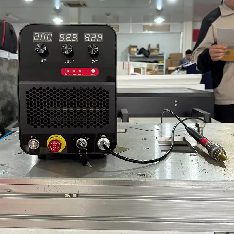
2. Critical Pulse Parameters Dictating Weld Integrity
To optimize a Pulsed Laser Spot Welding Machine for specific alloy profiles, engineers must program four interdependent energy vectors within the system controller:
Peak Pulse Power
Measured in kilowatts (kW), peak power represents the maximum optical output achieved during the pulse duration. High peak power is necessary to overcome the surface reflectivity of conductive non-ferrous metals like copper, gold, aluminum, and silver upon initial beam impingement.
Pulse Duration (Pulse Width)
Expressed in milliseconds (ms, typically 0.1 ms to 20 ms), pulse duration dictates the depth of thermal conduction into the joint interface. Shorter durations (under 2 ms) perform surface tacking and thin-wire joining without melt-through, while longer durations enable deeper keyhole penetration on structural metal tabs.
Pulse Frequency (Repetition Rate)
Measured in Hertz (Hz), frequency determines how many individual laser pulses fire per second. Lower frequencies (1 Hz to 5 Hz) are selected for manual, microscope-guided spot positioning, whereas higher frequencies (10 Hz to 50 Hz) enable continuous, overlapping seam welding on automated CNC stages.
Pulse Waveform Shaping
Advanced Fwincnc pulsed welders allow customization of the pulse shape itself (such as ramp-up, square wave, or ramp-down profiles). Ramping down the energy gradually at the tail end of the pulse slows the solidification rate of the molten pool, preventing shrinkage cratering and hot-cracking in sensitive alloys.
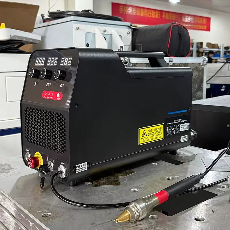
Technical Comparison: Pulsed Laser vs. Resistance Spot Welding
| Performance Parameter | Pulsed Laser Spot Welding Machine | Resistance Spot Welding (RSW) |
| Contact Geometry | Non-contact optical delivery | Physical mechanical electrode clamping |
| Heat-Affected Zone (HAZ) | Extremely narrow (< 0.2 mm) | Broad thermal spreading across joint |
| Minimum Weld Spot Diameter | 0.1 mm precision focal capability | 3.0 mm electrode contact limitation |
| Electrode Wear & Maintenance | Zero physical contact; no tool wear | High; constant copper tip dressing required |
| Dissimilar Metal Joining | High success rate (e.g., Copper to Steel) | Extremely limited due to electrical resistance gaps |
3. Systematic Setup Procedure for Micro-Welding Operations
To achieve consistent tensile strength and defect-free joints when configuring a Pulsed Laser Spot Welding Machine, operators should follow this standard setup sequence:
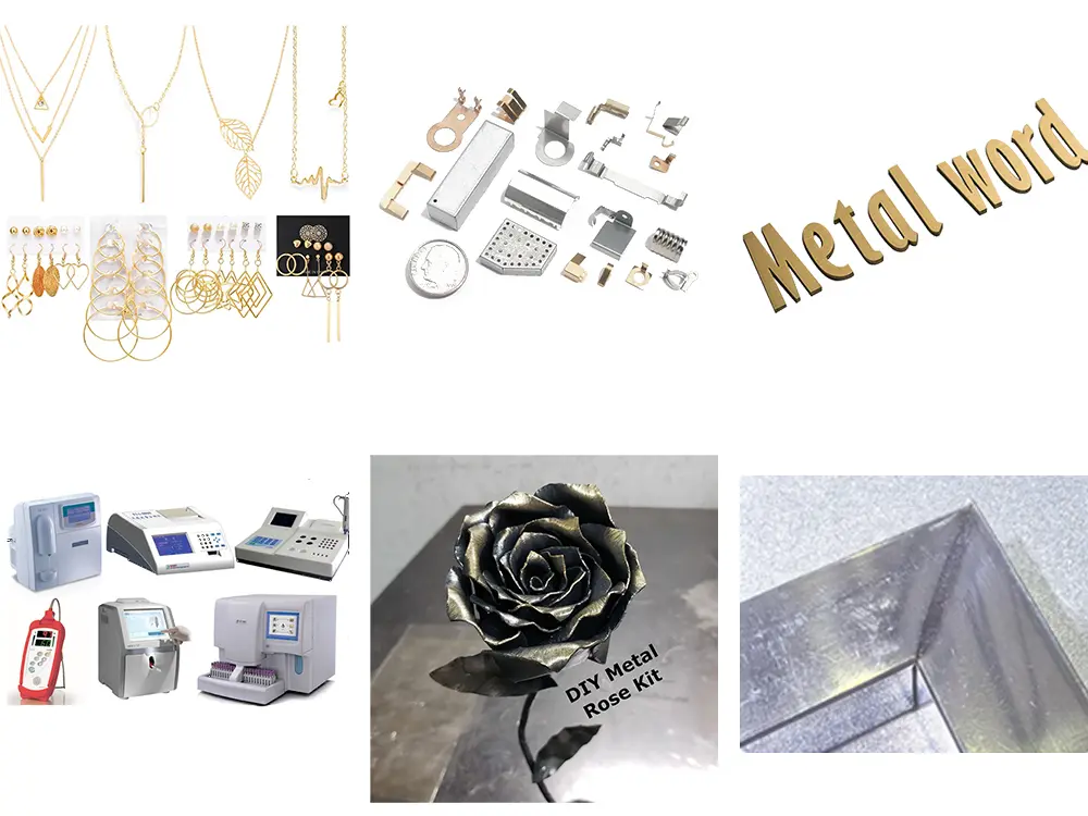
4. Primary Industrial Applications
The precise energy control of a Pulsed Laser Spot Welding Machine makes it indispensable across several specialized manufacturing sectors:
-
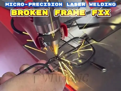
Jewelry Manufacturing & Repair: Seamlessly sizing platinum, gold, and silver rings, re-tipping watch bezel prongs, and repairing delicate filigree without removing heat-sensitive gemstones.
-
Electronics & Battery Tab Joining: Spot-welding nickel tabs onto lithium-ion battery cells without transmitting damaging heat into the internal chemical core.
-
Medical Device Assembly: Hermetically sealing surgical instruments, endoscopes, and pacemaker titanium housings under strict cleanroom conditions.
-
Precision Mold Repair: Depositing matching wire alloys into microscopic cracks or worn ejector pin holes on injection molds without thermal sinking or sink marks.
By pairing a Pulsed Laser Spot Welding Machine with Fwincnc motion control and optical monitoring accessories, manufacturers achieve reproducible, high-yield micro-joining performance across all production cycles.